For this holiday-light assignment, I used three separate LEDs from my kit. Each has its own output pin and resistor. Red, green, and blue blink at different rates, making a combined pattern that repeats every six seconds.
Circuit and schematic
| LED | Arduino pin | Series resistor | On / off interval | Full cycle |
|---|---|---|---|---|
| Red | D7 | 330 Ω | 500 ms / 500 ms | 1 second |
| Green | D6 | 330 Ω | 750 ms / 750 ms | 1.5 seconds |
| Blue | D5 | 330 Ω | 1000 ms / 1000 ms | 2 seconds |
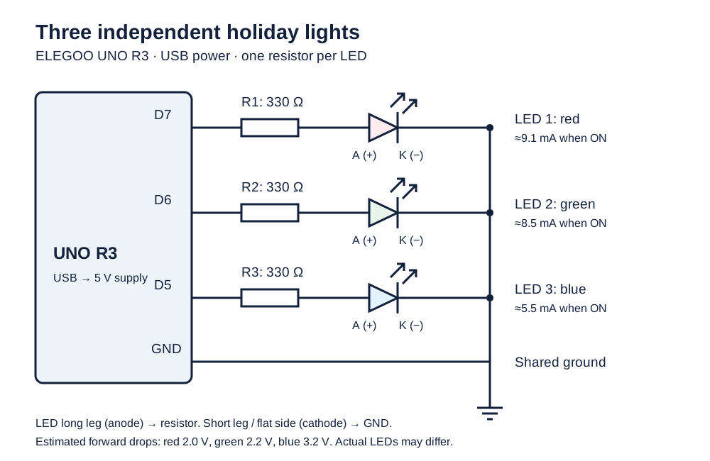
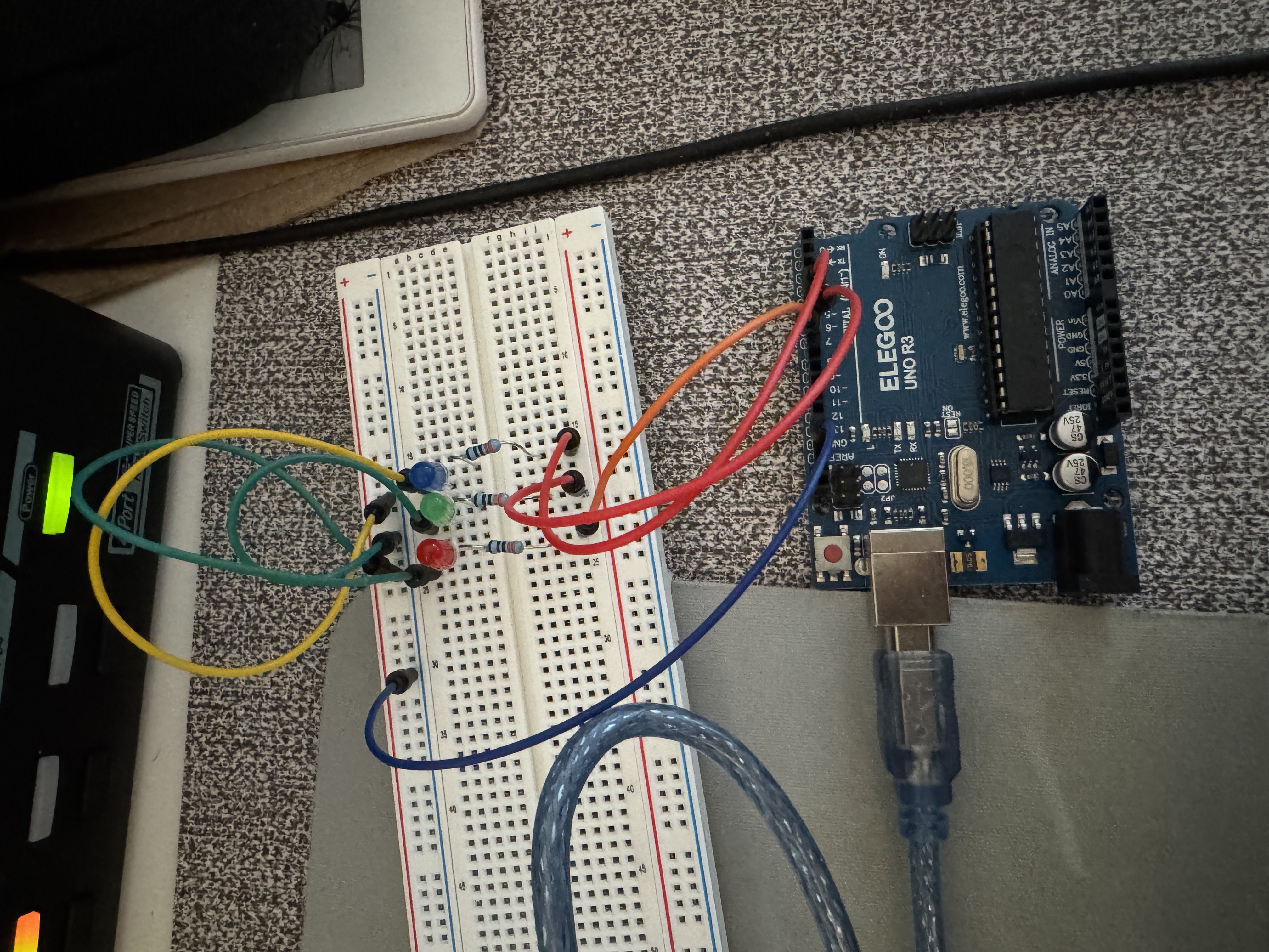
Each branch is output pin → resistor → LED anode → LED cathode → ground. The long LED lead normally identifies the anode; the short lead and flat side identify the cathode.
Resistor calculations
For a nominal 5 V HIGH output, I assume forward drops of 2.0 V for red, 2.2 V for green, and 3.2 V for blue. These are design estimates, not measured kit specifications; some green LEDs have substantially higher forward drops.
For red, targeting approximately 10 mA:
R = (Voutput − Vforward) / Itarget
R = (5 V − 2 V) / 0.010 A
R = 300 Ω
I chose 330 Ω, the next larger available kit value, and used one per LED.
| LED | Estimated current calculation | On-current |
|---|---|---|
| Red | (5 − 2.0) / 330 A | 9.1 mA |
| Green | (5 − 2.2) / 330 A | 8.5 mA |
| Blue | (5 − 3.2) / 330 A | 5.5 mA |
Using unrounded values, all three draw about 23.0 mA when on simultaneously, or 11.5 mA averaged over their 50% duty cycles. These figures exclude the UNO’s own current. Equal resistors do not guarantee equal perceived brightness.
Firmware
Each LED has its own timer and state. The sketch checks millis() instead of blocking with delay(), so one LED’s waiting period does not pause the others. All LEDs start off. Every meaningful code line has an explanatory comment immediately above it.
// Store the number of LEDs controlled independently.
const byte LED_COUNT = 3;
// Assign each LED its own UNO digital output pin.
const byte LED_PINS[LED_COUNT] = {7, 6, 5};
// Set each LED's time between state changes in milliseconds.
const unsigned long TOGGLE_MS[LED_COUNT] = {500, 750, 1000};
// Store a separate timing reference for each LED.
unsigned long lastToggle[LED_COUNT] = {0, 0, 0};
// Track each LED's on/off state, starting with all LEDs off.
bool ledIsOn[LED_COUNT] = {false, false, false};

// Run the initialization once after reset.
void setup() {
  // Visit every LED to initialize its pin.
  for (byte i = 0; i < LED_COUNT; i++) {
    // Configure this LED's pin as an output.
    pinMode(LED_PINS[i], OUTPUT);
    // Start this LED switched off.
    digitalWrite(LED_PINS[i], LOW);
  }
  // Read a common starting time after pin initialization.
  const unsigned long startTime = millis();
  // Visit every LED to initialize its timer.
  for (byte i = 0; i < LED_COUNT; i++) {
    // Start this LED's timer at the common starting time.
    lastToggle[i] = startTime;
  }
}

// Repeat continuously to update all three independent timers.
void loop() {
  // Read the current time once for this pass through the loop.
  const unsigned long now = millis();
  // Check each LED's timer without pausing the other LEDs.
  for (byte i = 0; i < LED_COUNT; i++) {
    // Use unsigned subtraction to check elapsed time across millis rollover.
    if (now - lastToggle[i] >= TOGGLE_MS[i]) {
      // Advance this timer by its interval to preserve its schedule.
      lastToggle[i] += TOGGLE_MS[i];
      // Change this LED to the opposite on/off state.
      ledIsOn[i] = !ledIsOn[i];
      // Set this LED's output high when on and low when off.
      digitalWrite(LED_PINS[i], ledIsOn[i] ? HIGH : LOW);
    }
  }
}
Circuit operation
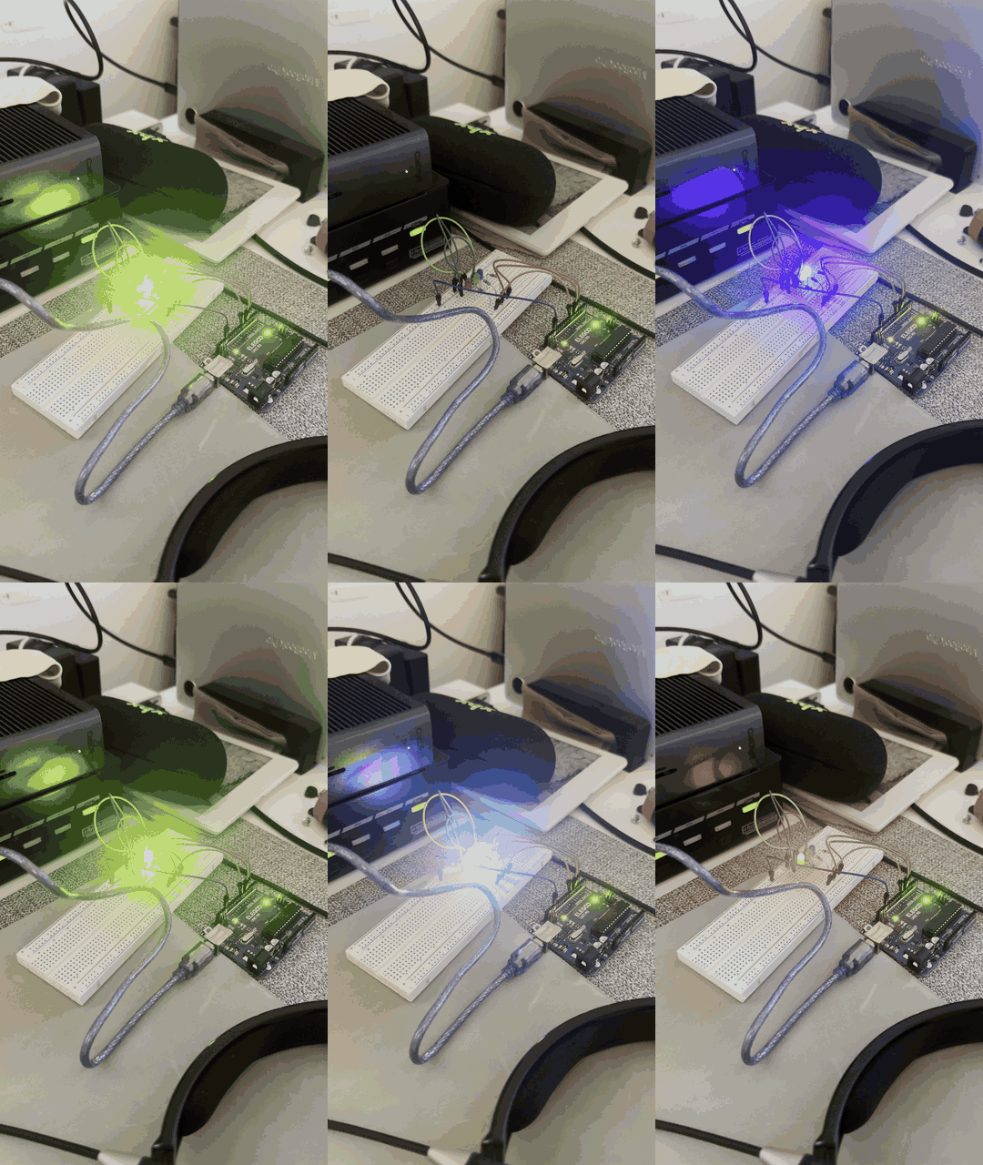
The cycle lengths are 1, 1.5, and 2 seconds. Their smallest common repeat time is 6 seconds, so the LEDs repeatedly move into and out of alignment.
Questions
1. Voltage across the LEDs over time
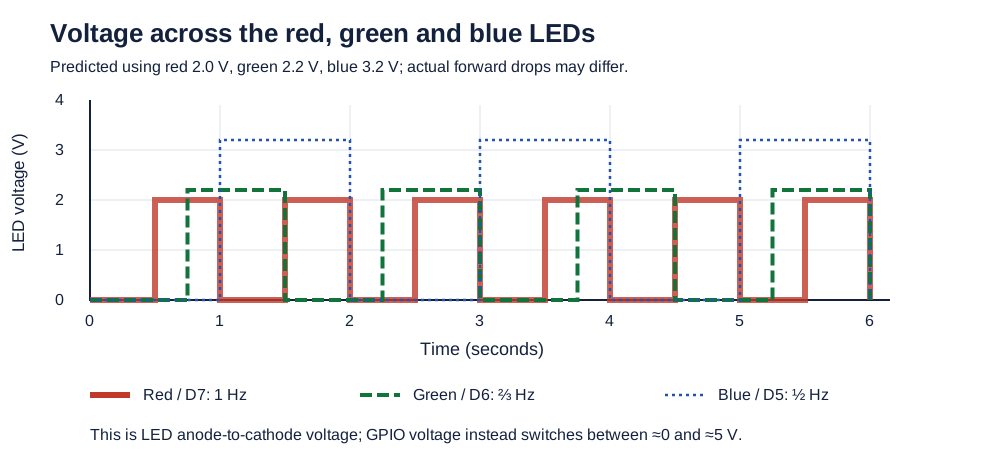
The GPIO switches between approximately 0 and 5 V, but the LED itself does not have the full 5 V across it. For red, about 2 V is across the LED and the remaining 3 V is across its resistor.
2. How many LEDs could blink independently, and how much current would they draw?
With one GPIO per LED, the UNO R3 has 14 digital header pins plus six analog pins usable as digital outputs, for a theoretical total of 20.
For a large circuit as such, 18 LEDs split equally into six red, six green, and six blue, each with 330 Ω, would draw approximately 6 × 23.03 mA = 138.2 mA when all are on.
The pin count does not mean every pin can simultaneously supply 20 mA. The Arduino has a 200 mA maximum through its pins, including its own consumption. For a lower-current 20-LED example, red LEDs with 1 kΩ each would draw approximately 20 × 3 mA = 60 mA when all are on. External drivers can control additional LEDs beyond the direct GPIO count.
3. How fast must the LEDs blink before blinking is no longer visible?
This would probably vary person to person, at some point after 90hz I can not longer tell that the LED is blinking, but I still feel like when I look closely at the bulb.
4. AI Statement
AI was used to format this Markdown document as well as generating alt texts for non-text media.